Definition of the Mechanical and Electronic Design of High Boy

Developing hardware is a completely different beast compared to software. You can push software updates every day, but with hardware, every single change means going through a full fabrication cycle just to produce test samples. For the last two months, we’ve been heads-down on the schematics and mechanical design. We are finally closing in on freezing the BOM and moving toward our first prototype run.
In this post, we will detail the decisions we have made so far
Why two PCBs?
The High Boy has a lot of RF activity happening simultaneously: NFC (13.56 MHz), RFID (125 kHz), Sub-GHz (315-915 MHz via CC1101), Wi-Fi (ESP32-C5), and LoRa. Originally, the plan was to fit everything onto a single board to keep manufacturing simpler and cheaper.
The problem is EMI. The NFC frontend is incredibly sensitive. When it shares a board with Sub-GHz and Wi-Fi radios, crosstalk between the subsystems degrades reception performance. Other devices in this category including several we analyzed during R&D separate the NFC board from the rest for this exact reason.
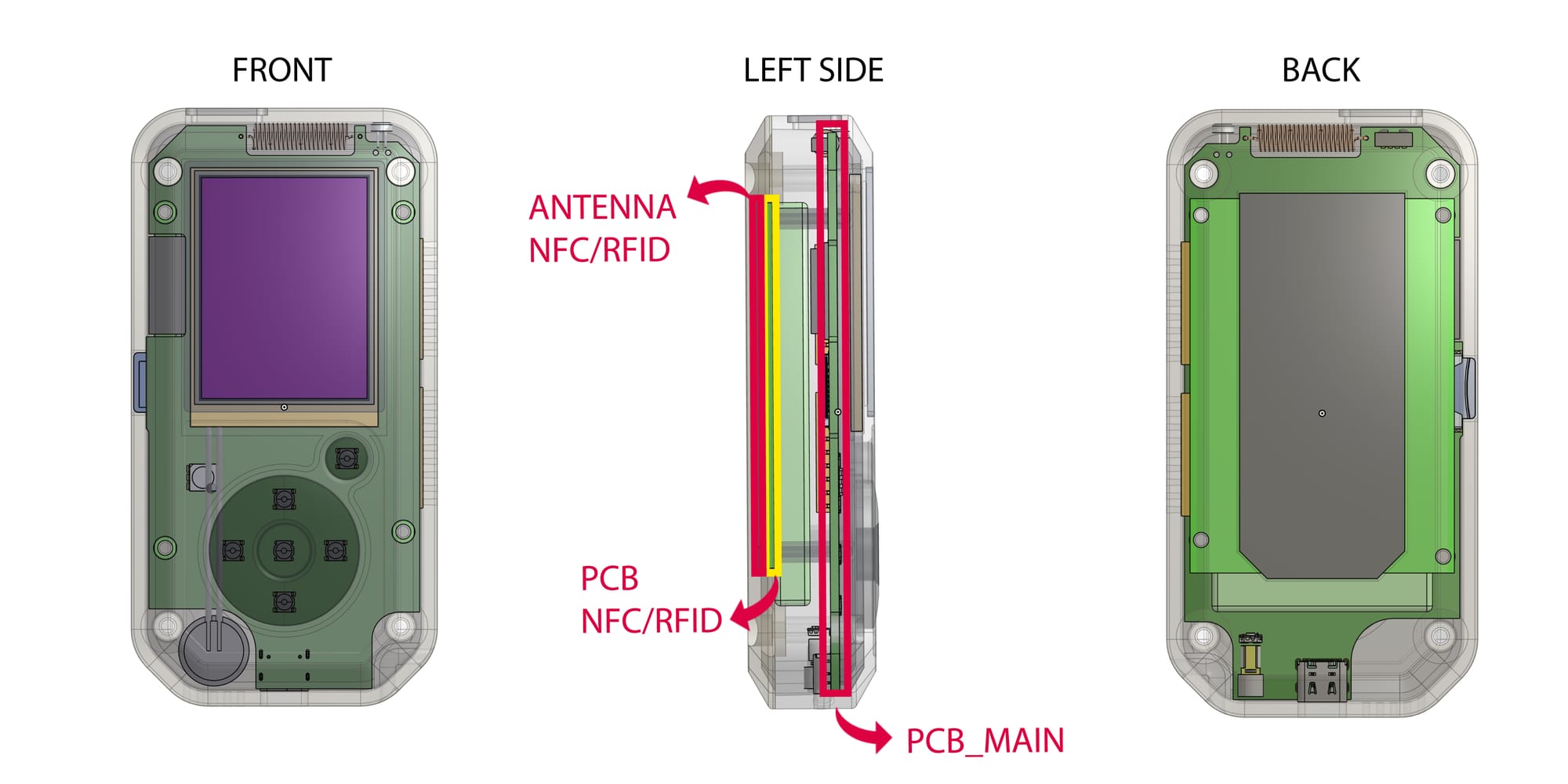
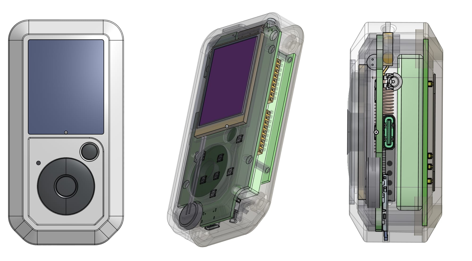
As a result, the High Boy features two boards:
- Main Board: Houses the ESP32-P4, ESP32-C5, power circuitry, Sub-GHz, LoRa, audio, and display.
- Secondary Board: Dedicated solely to NFC/RFID, positioned behind the battery with a dual-band antenna.
This adds about 3mm to the device's thickness, but we’d rather guarantee solid RF performance than optimize for thinness. We plan to test a single-PCB design in a future revision once we have real-world performance data.
The Sub-GHz Antenna and the "8mm Problem"
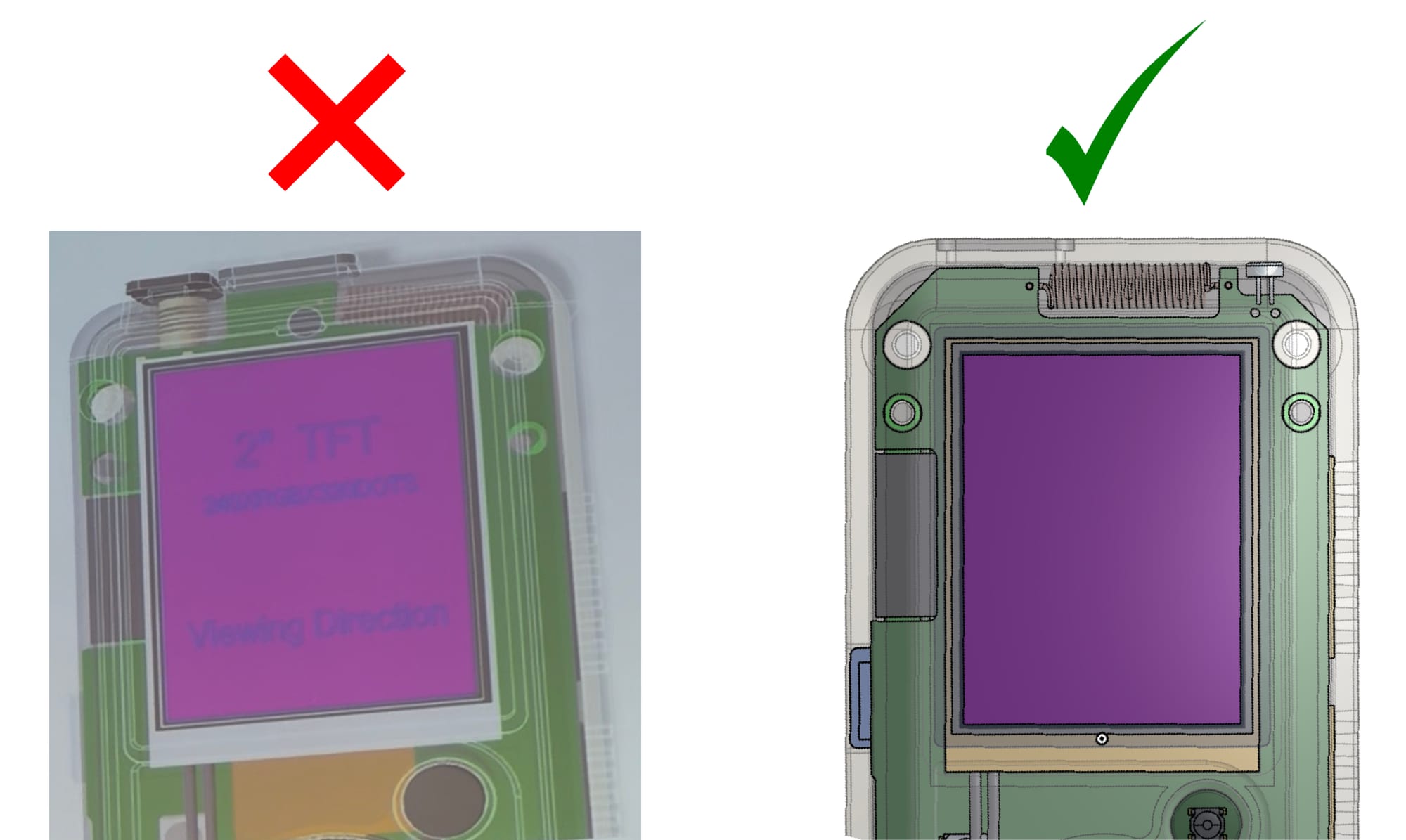
The High Boy uses a helical Sub-GHz antenna covering 315, 433, 868, and 915 MHz, located at the top of the device. Directly below it sits the display, which has a metallic backplane.
Antenna subsystems are more complex than they look. Metal near an antenna causes detuning—essentially, the antenna loses its "tune," and most of the energy is absorbed rather than radiated. In our initial layout, the display was simply too close.
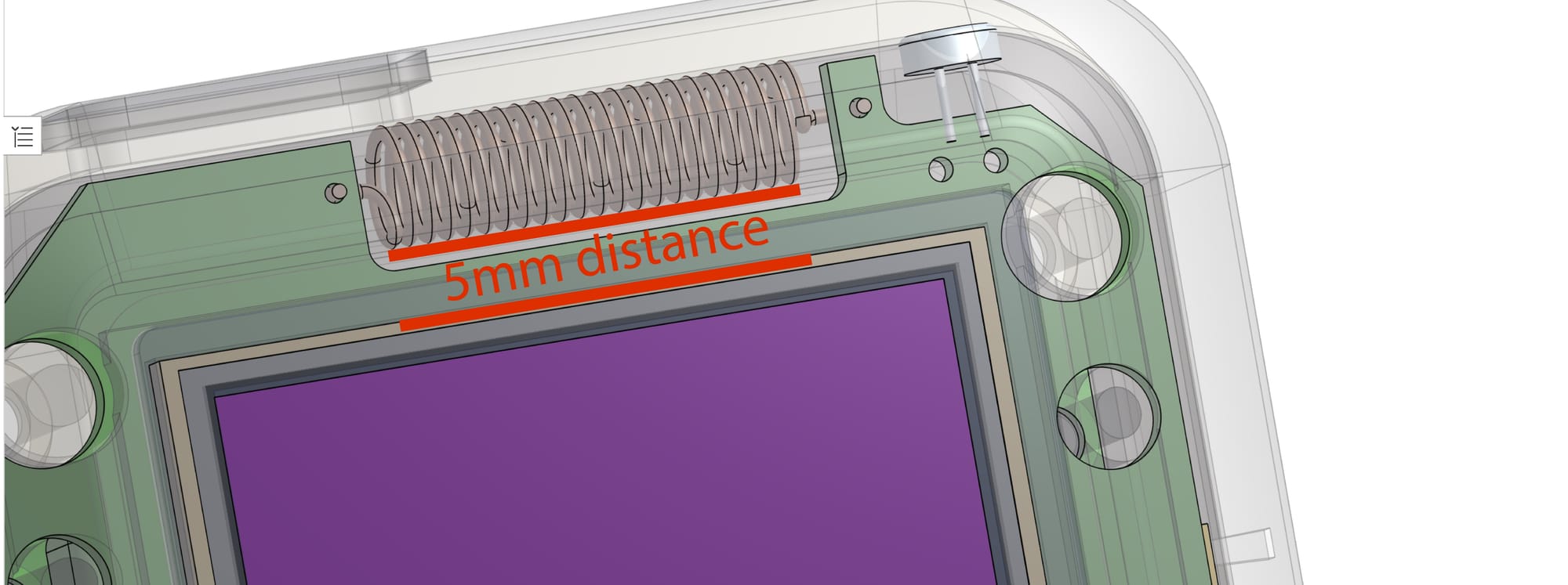
Our engineer recommended a minimum of 7mm clearance, with 8mm+ being ideal. (50mm would be perfect, but that’s impossible in a handheld). Our solution was to shift the display 8–12mm downward within the enclosure. The buttons moved with it. While this changed the ergonomics slightly—the screen sits a bit lower—it gives the antenna the "breathing room" it needs to function correctly.
Why the SMA Connector was a No-Go
One of our most-asked questions is about external antennas. We initially planned to include an SMA connector at the top for high-gain antennas, but we had to pull it.
The reason? FCC Certification. Current regulations regarding external antenna connectors on consumer devices complicate the process significantly, especially for a first-batch production where we need to pass certification without delays.
Instead, we will use an internal FPC antenna adhered to the left side of the housing, covering 868 MHz and 915 MHz. While the performance is naturally lower than an external antenna, it is more than sufficient for standard use cases.
· · ·
GPIOs compatible with Flipper Zero modules.
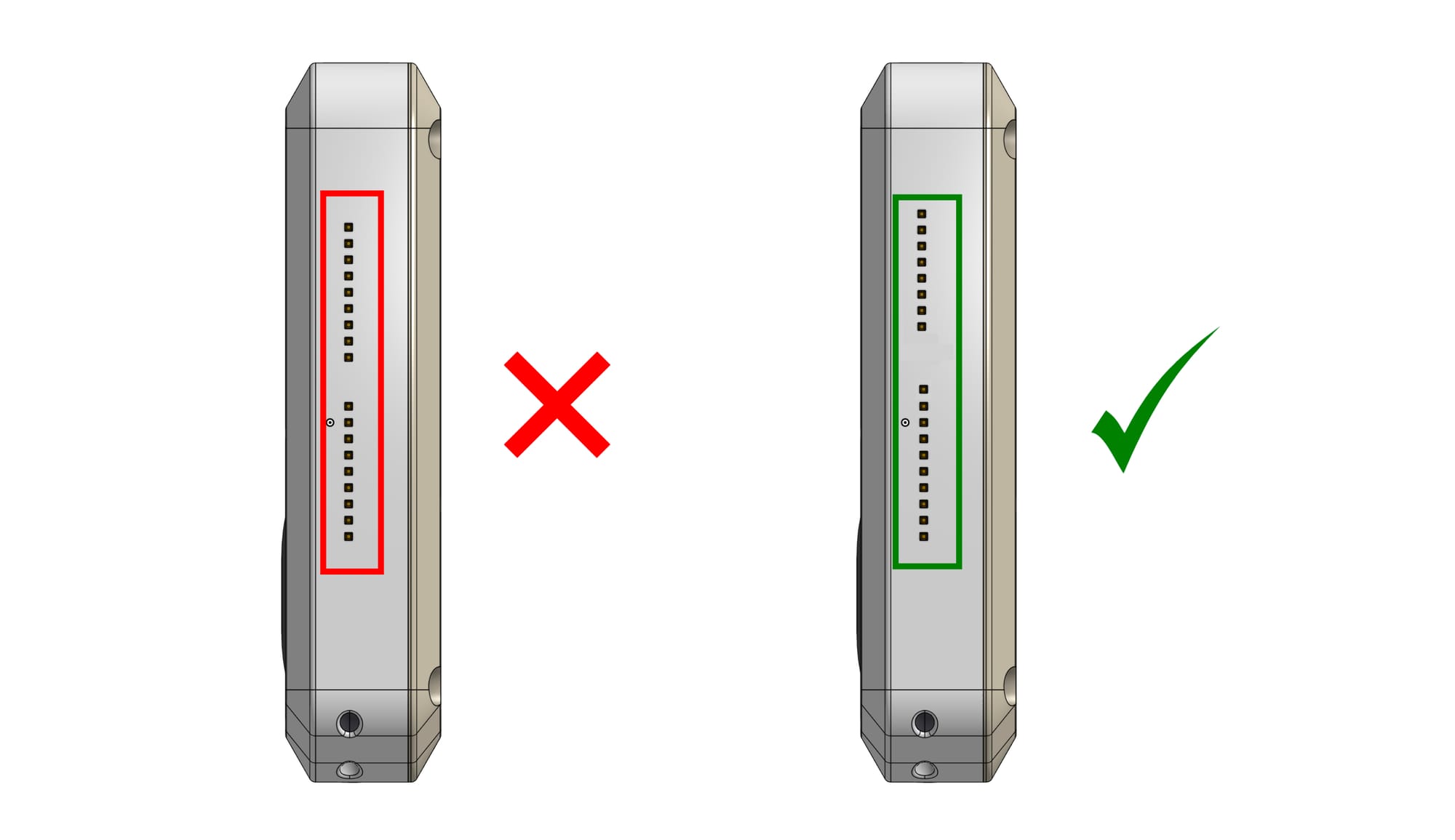
The High Boy’s GPIO connector will use the exact same pinout and physical dimensions as the Flipper Zero. Modules made for the Flipper will plug right into the High Boy. There are already hundreds of modules using this specific footprint, and it made no sense to create a different connector just for the sake of being different
Next Steps
The schematic is currently undergoing rework. We still need to update the power sheet and audio section, finish integrating the BMI270 (IMU), and refine the 125 kHz circuit. Currently, we’re looking at 5 sheets in Altium with 155 components. We estimate 1 to 4 weeks for the full update.
In parallel, we are finalizing the mechanical enclosure. We expect a physical prototype by early April. After that comes RF validation, integration testing, and preparation for the "risk lot" and pilot runs.
We are incredibly excited about the pace of this project. We can't wait to show you the new prototype. Thank you all for the support—let's do this!